English
 русский
 Español
 عربى
عربى

Content
- 1 Clutch Hydraulic Pumps and 2-Way Hydraulic Pumps: The Core Distinction
- 2 How a Clutch Hydraulic Pump Works
- 3 How a 2-Way Hydraulic Pump Works
- 4 Clutch Hydraulic Pump vs. 2-Way Hydraulic Pump: Comparison Table
- 5 Key Specifications to Evaluate When Selecting Either Pump Type
- 6 When a 2-Way Pump Serves as the Power Source for a Clutch Hydraulic System
- 7 Common Problems and Diagnostic Indicators
- 8 Maintenance Practices That Extend Pump Service Life
Clutch Hydraulic Pumps and 2-Way Hydraulic Pumps: The Core Distinction
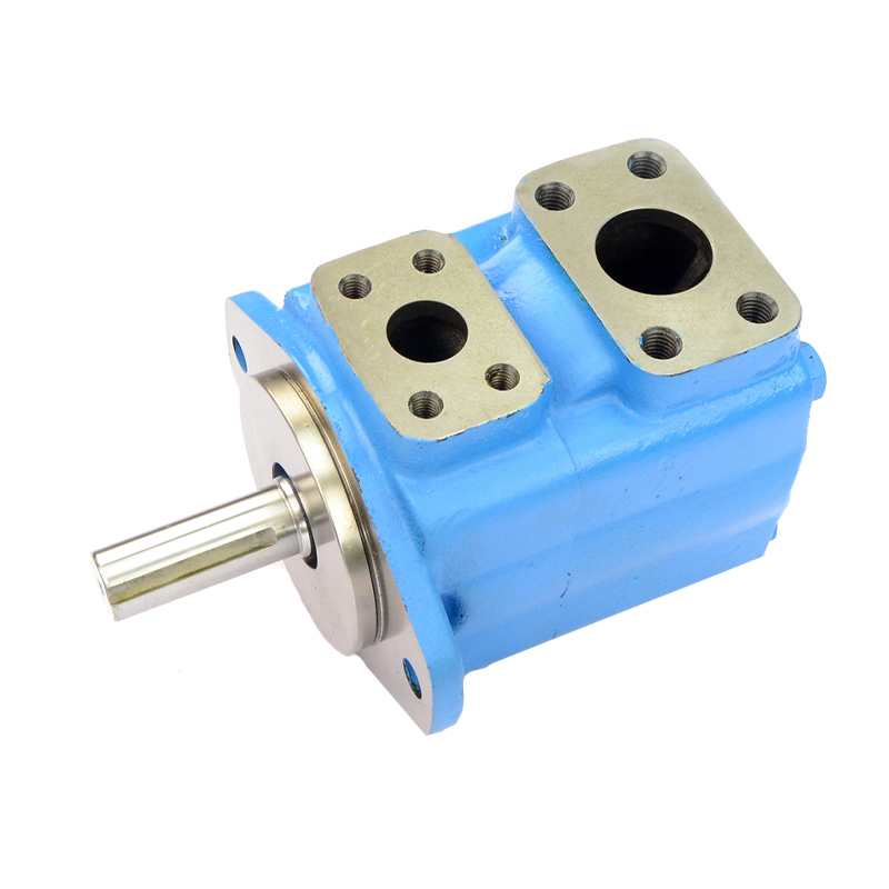
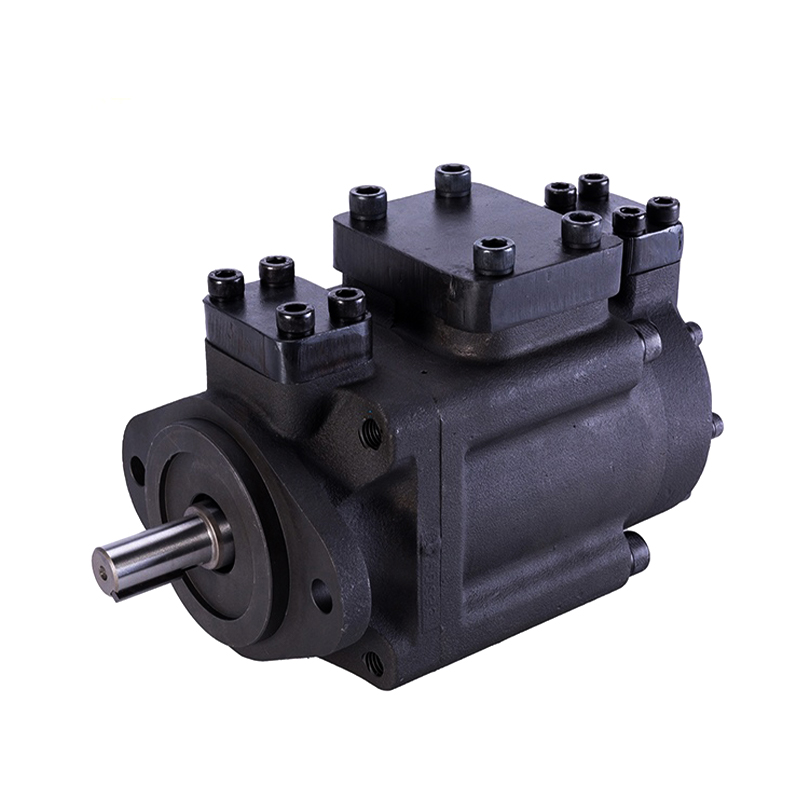
A clutch hydraulic pump is a purpose-built unit that generates and maintains the hydraulic pressure needed to engage or disengage a clutch mechanism—most commonly in heavy vehicles, agricultural machinery, and industrial drivetrains. A 2-way hydraulic pump, by contrast, is a directional pump capable of delivering pressurized fluid in two directions, allowing it to extend and retract a hydraulic cylinder or reverse a hydraulic motor without additional valve assemblies.
These are not interchangeable categories. A clutch hydraulic pump is defined by its application—what it controls. A 2-way hydraulic pump is defined by its flow direction capability—how it moves fluid. In some systems, such as reversible hydraulic clutch actuators, a 2-way pump may serve as the power source for a clutch hydraulic circuit. Understanding both types individually, and where they intersect, is essential for correct selection and system design.
How a Clutch Hydraulic Pump Works
A clutch hydraulic pump generates controlled hydraulic pressure that acts on a clutch slave cylinder or actuator piston. When the driver or control system commands clutch disengagement, the pump builds pressure that pushes the piston against the clutch release bearing, separating the friction disc from the flywheel. When pressure is released or reversed, a return spring or counter-pressure re-engages the clutch.
In automotive applications, the clutch hydraulic pump is often the master cylinder—a small piston pump actuated directly by the clutch pedal. In automated manual transmissions (AMTs) and heavy-duty commercial vehicles, a dedicated electrohydraulic clutch pump replaces the mechanical linkage entirely, generating pressures typically between 20 and 80 bar (290–1,160 psi) depending on clutch clamping force requirements.
Key Components of a Clutch Hydraulic Pump System
- Pump unit: Generates pressure from an electric motor or mechanical drive. Gear pumps and piston pumps are most common in this role.
- Accumulator: Stores pressurized fluid so the pump does not need to run continuously during clutch operations—critical in automated transmission systems where clutch engagement must be near-instantaneous.
- Solenoid valve: Controls the direction and timing of fluid flow to the actuator, replacing the mechanical function of a clutch pedal in automated systems.
- Slave cylinder / actuator: Converts hydraulic pressure back into mechanical force to act on the clutch release mechanism.
- Reservoir and fluid lines: Store hydraulic fluid (typically DOT 4 brake fluid or dedicated hydraulic oil) and connect system components.
Common Applications of Clutch Hydraulic Pumps
- Heavy trucks and buses with automated manual transmissions (AMTs)
- Agricultural tractors with hydraulic PTO and wet clutch systems
- Industrial machinery with clutch-brake combinations (printing presses, punch presses)
- Marine transmissions where remote clutch control is required
- Performance and racing vehicles using hydraulic clutch assist systems
How a 2-Way Hydraulic Pump Works
A 2-way hydraulic pump—also called a bidirectional or reversible hydraulic pump—can pressurize fluid in either of two output ports depending on its rotation direction or internal valve configuration. When Port A is the pressure outlet, Port B becomes the return (tank) side, and vice versa. This allows a single pump to both extend and retract a double-acting cylinder, or to drive a hydraulic motor in forward and reverse, without requiring external directional control valves.
The most common pump types used in 2-way configurations are gear pumps (particularly external gear pumps) and axial piston pumps. Gear pumps achieve bidirectional flow by reversing motor rotation—their internal geometry allows symmetric flow in either direction. Axial piston pumps can achieve bidirectional output through over-center swashplate control without reversing shaft rotation, which is particularly useful in closed-loop hydrostatic transmission circuits.
2-Way vs. 1-Way Pump: What Changes in Practice
A standard (unidirectional) hydraulic pump has one pressure port and one inlet. It requires a separate directional control valve (typically a 4/3 or 4/2 solenoid valve) to reverse actuator movement. A 2-way pump eliminates this valve requirement for simple extend/retract or forward/reverse applications, reducing system component count, potential leak points, and pressure drop losses across the valve body.
In a compact power unit powering a single double-acting cylinder—such as a hydraulic log splitter, tail lift, or small press—a 2-way pump paired with a reversible electric motor can replace an entire valve manifold assembly. This is why 2-way pumps are popular in space-constrained or weight-sensitive mobile hydraulic applications.
Clutch Hydraulic Pump vs. 2-Way Hydraulic Pump: Comparison Table
| Characteristic | Clutch Hydraulic Pump | 2-Way Hydraulic Pump |
|---|---|---|
| Primary function | Actuate clutch engagement/disengagement | Deliver pressurized flow in two directions |
| Defined by | Application (clutch control) | Flow direction capability |
| Typical pressure range | 20–80 bar (290–1,160 psi) | 10–350+ bar depending on pump type |
| Flow direction | Typically unidirectional (valve-controlled reversal) | Bidirectional (pump-level reversal) |
| Common pump types used | Gear pump, piston pump, master cylinder | External gear pump, axial piston pump |
| Requires directional valve? | Often yes (solenoid valve for automated systems) | Not always—pump handles direction |
| Typical fluid | DOT 4 brake fluid or hydraulic oil | Hydraulic oil (ISO VG 32–68) |
| Key application examples | Trucks, tractors, AMT systems, marine | Log splitters, tail lifts, presses, hydrostatic drives |
Key Specifications to Evaluate When Selecting Either Pump Type
Whether you are sourcing a replacement clutch hydraulic pump or specifying a 2-way pump for a new system, several parameters directly determine whether the pump will perform reliably in your application.
Pressure Rating (Bar / PSI)
Always match the pump's maximum rated pressure to the system's peak demand, with a safety margin of at least 20–25%. A clutch system requiring 50 bar actuation pressure should use a pump rated for at least 60–65 bar continuous. For 2-way pumps in cylinder applications, calculate the required pressure from the load force divided by the cylinder bore area: P (bar) = Force (N) ÷ Area (mm²) × 10.
Flow Rate (L/min or GPM)
Flow rate determines actuator speed. For clutch systems, response time is critical—automated clutch systems typically require engagement within 150–400 milliseconds, which dictates minimum pump flow rate in combination with accumulator volume. For 2-way pumps driving cylinders, calculate required flow from cylinder volume divided by desired cycle time.
Drive Type: Electric Motor vs. PTO vs. Engine-Driven
- Electric motor driven: Most common for standalone clutch hydraulic pump units and compact 2-way power packs. Allows on-demand operation independent of engine speed. Typical motor ratings range from 0.37 kW to 7.5 kW for mobile applications.
- PTO driven: Common on agricultural and industrial equipment where the tractor or engine's power take-off shaft drives the pump directly. Provides high power density but ties pump operation to engine speed.
- Engine-driven (crankshaft mounted): Found in many OEM clutch hydraulic systems on heavy trucks, where the pump runs off the engine accessory drive and charges an accumulator continuously.
Displacement and Volumetric Efficiency
Pump displacement (cc/rev) combined with shaft speed (RPM) determines theoretical flow output. Volumetric efficiency—typically 85–98% for gear pumps and 90–98% for piston pumps—accounts for internal leakage. As system pressure increases, volumetric efficiency decreases, which must be factored into flow calculations for high-pressure clutch or bidirectional applications.
When a 2-Way Pump Serves as the Power Source for a Clutch Hydraulic System
Some advanced clutch actuation systems—particularly in agricultural machinery, marine transmissions, and industrial clutch-brake combinations—use a 2-way pump as the core pressure-generating element. In these configurations, reversing the pump's flow direction directly controls the extend/retract action of a double-acting clutch actuator cylinder, eliminating the solenoid directional valve from the pressure circuit.
This architecture offers two practical advantages: fewer failure points in the hydraulic circuit (no directional valve spool to stick or seal to leak) and faster pressure response because there is no valve switching delay between the pump and actuator. The trade-off is that the electric motor driving the pump must be capable of bidirectional rotation and rapid reversal, which requires a suitable motor controller or reversing starter.
A practical example is the hydraulic wet clutch control system used on certain John Deere and Case IH tractor transmissions, where a reversible gear pump assembly manages clutch pack engagement pressure with sub-200ms response times across a pressure range of 15–45 bar.
Common Problems and Diagnostic Indicators
Clutch Hydraulic Pump Failure Signs
- Slow or incomplete clutch engagement/disengagement: Indicates insufficient pressure output—check pump output pressure against specification and inspect for internal wear or seal degradation.
- Clutch slipping under load: Can result from pressure that drops under demand—verify accumulator precharge pressure and pump output at operating RPM.
- Fluid leaks at pump body or line fittings: Common with worn shaft seals or cracked pump housings—most evident after heat cycling.
- Noisy pump operation (whining or cavitation): Suggests air ingestion, low fluid level, or a restricted inlet filter—address immediately to prevent rapid internal wear.
2-Way Hydraulic Pump Failure Signs
- Actuator moves in one direction only: If the cylinder extends but will not retract (or vice versa), suspect a failed check valve within the pump body, a seized gear set, or a motor that cannot reverse—isolate each component systematically.
- Reduced speed in both directions: Points to worn gear or piston clearances reducing volumetric efficiency—measure actual flow output and compare to rated specification.
- Overheating: Excessive internal bypass due to worn components causes fluid to recirculate internally, generating heat without useful output—install a temperature gauge on the return line to confirm.
- Pressure not reaching setpoint: Check the relief valve setting first—a relief valve that has drifted low will limit maximum system pressure regardless of pump condition.
Maintenance Practices That Extend Pump Service Life
Both clutch hydraulic pumps and 2-way hydraulic pumps share common maintenance requirements that, when followed consistently, significantly extend operational life and reduce unplanned downtime.
- Use the correct fluid and maintain fluid cleanliness. Contaminated hydraulic fluid is responsible for the majority of premature pump failures. Target an ISO cleanliness level of 16/14/11 or better for gear pumps and 15/13/10 for piston pumps. Use a 10-micron return filter as a minimum.
- Change fluid and filters at manufacturer-specified intervals. For most mobile hydraulic systems, this means every 1,000–2,000 operating hours or annually—whichever comes first.
- Check and maintain reservoir fluid level. Running a pump with a low reservoir causes cavitation, which generates micro-bubbles that implode on internal pump surfaces, causing accelerated erosion of gear teeth and piston faces.
- Inspect shaft seals and port fittings regularly. A small external leak that is ignored will worsen as fluid loss lowers reservoir level, eventually leading to severe pump damage.
- Monitor operating temperature. Sustained hydraulic fluid temperatures above 80°C (176°F) accelerate fluid degradation and reduce seal life. Install a cooler if the system consistently exceeds this threshold under normal operating conditions.