


 русский
 Español
 عربى
عربى

Hydraulic vane motors are the definitive rotary actuator when an application cannot tolerate speed ripple, noise, or poor low‑speed control. Their balanced internal design converts hydraulic flow into exceptionally smooth shaft rotation, with starting torque consistently reaching 90–95% of running torque. This makes them the preferred drive for plastic injection molding screws, marine winches, large conveyor systems and rotary kilns. In continuous industrial service, a correctly sized and maintained vane motor routinely surpasses 20,000 operating hours before requiring major overhaul, all while operating at sound levels 10–20 dB(A) lower than equivalent piston motors.
Content
Operating Principle of a Balanced Vane Motor
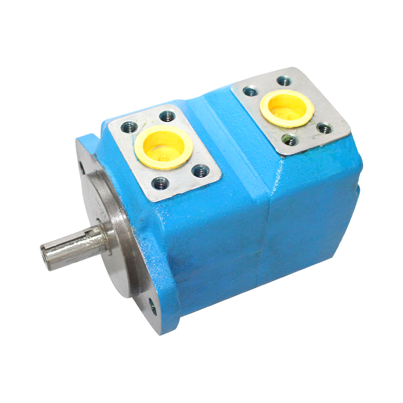
A vane motor works in the reverse manner of a vane pump. Pressurised oil enters inlet ports in the cam ring, pushing against the exposed area of the vanes that are extended from the slotted rotor. Because the cam ring is oval‑shaped and the rotor is centred, the pressure force creates an unbalanced torque on the rotor shaft. As the rotor turns, the vanes follow the contour of the cam ring, and spent fluid is carried to the outlet port. The dual inlet and outlet ports balance the hydraulic forces on the rotor bearings, eliminating the radial side load that characterises gear motors. This hydraulic balance is what gives the vane motor its extremely smooth rotation and long bearing life.
Most industrial vane motors use a double‑vane or intra‑vane design, where a smaller spring‑loaded vane inside the main vane ensures continuous contact with the cam ring even during start‑up when centrifugal force is absent. This guarantees immediate torque delivery and contributes to the motor’s excellent low‑speed behaviour.
Key Performance Advantages of Vane Motors
Exceptional Starting Torque
The ability to develop high torque from zero speed is where vane motors shine. Because the vanes are pressure‑loaded against the cam ring the instant oil enters, a balanced vane motor delivers 90–95% of its rated running torque at breakaway. By comparison, an axial piston motor typically achieves 85–90%, and a gear motor only 70–80%. On a heavy‑duty winch that must lift a 30‑tonne load from a dead stop, this near‑instant torque eliminates the need for oversizing the motor and prevents the load from slipping backwards on start‑up.
Smooth, Ripple‑Free Low‑Speed Operation
Torque ripple in a vane motor is typically less than 3% of mean torque, compared to 8–15% for gear motors and 2–5% for multi‑piston motors. This smoothness allows stable operation at speeds as low as 10–20 rpm without the stick‑slip motion that plagues other motor types. A plastic injection molding plant that retrofitted its 450‑tonne machine screw drive with a vane motor reported that screw speed could be held to within ±0.5 rpm of setpoint, improving shot weight consistency by 1.2% and eliminating melt‑temperature spikes caused by uneven shear.
Quiet, Operator‑Friendly Operation
Without the reciprocating pistons that create pressure pulsation, vane motors generate significantly less audible noise. Typical sound pressure levels at 1 m are 60–72 dB(A) under full load, whereas a comparable piston motor may produce 78–88 dB(A). In a food‑processing conveyor application where operators work within a few metres of the hydraulic power unit, switching from piston to vane drive motors brought the ambient noise level from 85 dB(A) to below 75 dB(A), removing the requirement for mandatory hearing protection and reducing operator fatigue.
Vane Motors Compared: Gear, Vane, and Piston
Understanding where vane motors outperform alternatives—and where they have limits—is critical for proper hydraulic circuit design. The table below quantifies the main differences under typical industrial operating conditions.
| Parameter | Vane Motor | Gear Motor | Axial Piston Motor |
|---|---|---|---|
| Max continuous pressure | 175–210 bar | 210–250 bar | 350–450 bar |
| Starting torque (% of running torque) | 90–95% | 70–80% | 85–90% |
| Speed range (rpm) | 10–2,500 | 400–4,000 | 5–5,000 |
| Torque ripple | <3% | 8–15% | 2–5% |
| Noise level at full load (dB(A)) | 60–72 | 75–85 | 78–88 |
| Typical service life (hours) | 15,000–25,000 | 5,000–10,000 | 12,000–20,000 |
| Relative initial cost | Moderate | Low | High |
Vane motors are clearly the leader in low‑noise, high‑starting‑torque, and low‑ripple applications, though they are not the first choice for pressures above 250 bar. Their moderate cost and extended service life make them the most economical solution over a 10‑year ownership period in medium‑pressure continuous‑duty systems.
Industrial Applications Where Vane Motors Dominate
The unique combination of smooth rotation, high starting torque, and quiet operation makes vane motors the default choice in several demanding sectors.
Plastic Injection Molding and Extrusion
Screw rotation speed directly affects melt quality and shot weight. A vane motor’s ability to hold ±0.5 rpm across a wide speed range ensures consistent plasticising time and homogeneous melt temperature. A European packaging manufacturer replaced the gear motors on eight 300‑tonne presses with high‑response vane motors and documented a 7% reduction in reject parts over the first quarter, paying back the retrofit cost in under six months.
Marine Deck Winches and Capstans
Winches demand maximum torque from a dead stop to lift loads safely, often in wet and salty conditions. A set of 50‑tonne line‑pull winches on a research vessel were upgraded to VQ‑series balanced vane motors. At a system pressure of 200 bar, each motor produces 93% of running torque at breakaway, eliminating the need for a counterbalance valve kick‑open spike and giving the operator precise inching control when deploying sensitive oceanographic instruments.
Heavy Conveyor and Rotary Kiln Drives
Long troughed conveyors in mining and large‑diameter rotary kilns in cement plants benefit from vane motors’ smooth speed ramp‑up, which reduces mechanical stress on belts and couplings. A 250 m aggregate conveyor that was previously driven by two piston motors suffered repeated flexible coupling failures due to torque spikes. After switching to a single large‑displacement vane motor with a planetary gearbox, coupling life extended from an average of 4 months to over 2 years, and the motor noise at the operator platform dropped to 68 dB(A).
Selection and Installation Best Practices
Matching Displacement and Pressure to the Duty Cycle
Vane motors are available in fixed displacements from 5 to 300 cm³/rev. Selecting the correct size requires calculating not only the maximum torque demand but also the continuous torque envelope. Running a vane motor at its peak pressure for extended periods will shorten vane and cam‑ring life. A conservative design guideline is to size the motor so that the continuous operating pressure does not exceed 80% of its rated maximum. For a plasticising screw that requires a sustained 120 N·m at 200 rpm, a motor with a theoretical displacement of 50 cm³/rev and a pressure rating of 210 bar would operate at around 155 bar continuous, leaving a comfortable margin.
Fluid Cleanliness is Non‑Negotiable
The close‑fitting vanes and cam ring demand cleaner oil than gear motors. The target cleanliness level for mineral‑oil‑based fluids should be ISO 4406 18/16/13 or better. A full‑flow return filter with a β₁₀ ≥ 75 rating and a high‑pressure filter downstream of the pump are strongly recommended. In one documented case, a factory that neglected filtration saw its vane motor service life drop to under 4,000 hours due to vane‑tip erosion from silt‑sized particles. After upgrading to a 10 µm absolute high‑pressure filter, the next motor set achieved over 20,000 hours.
Drain Line and Case Pressure
Vane motors require a dedicated case drain line plumbed directly to the reservoir, with no back‑pressure. The maximum allowable case pressure is typically 2–3 bar. A pinched or blocked drain line will quickly cause the shaft seal to fail, leading to external leakage and possible vane‑path damage.
Maintenance Practices That Maximise Service Life
When the system is kept clean and the motor operates within its design envelope, preventive maintenance intervals can be extended significantly. The following practical steps have been shown to keep vane motors running reliably beyond 25,000 hours:
- Monitor case drain flow quarterly. A gradual increase indicates vane‑tip or pressure‑plate wear. If drain flow exceeds 10% of the motor’s rated flow, plan a cartridge replacement.
- Take oil samples every 500 hours. Rising iron or silicon particle counts are early warnings of cam‑ring abrasion or seal degradation.
- Keep the motor housing clean and check for hot spots with a thermal imager. A temperature difference of more than 10 °C between the inlet and outlet ports may signal excessive internal leakage.
- Use only genuine replacement cartridges that include matched vanes and cam rings. Mixing old and new wear components can accelerate failure.
By following these guidelines, operators consistently achieve the long, trouble‑free service that defines hydraulic vane motors as the most reliable medium‑pressure rotary drive technology available today.