English
 русский
 Español
 عربى
عربى

Content
- 1 Start with a Systematic Approach
- 2 Symptom 1 — Loss of Pressure or Power
- 3 Symptom 2 — Overheating
- 4 Symptom 3 — Abnormal Noise and Vibration
- 5 Symptom 4 — External and Internal Leaks
- 6 Symptom 5 — Slow or Erratic Actuator Movement
- 7 Pump-Specific Troubleshooting
- 8 Diagnostic Tools Every Technician Should Use
- 9 Preventive Maintenance to Avoid Repeat Failures
Start with a Systematic Approach
The most expensive mistake in hydraulic troubleshooting is changing parts before diagnosing the problem. A pump replaced on instinct costs time and money; a pump replaced after confirming it is the source of a measured pressure loss solves the problem permanently. Systematic troubleshooting begins with information, not tools.
Before touching any component, locate the hydraulic schematic for the system. Tracing the flow path on paper takes minutes and frequently reveals the fault location before a single fitting is loosened. Valves buried inside manifolds, pilot lines feeding remote actuators, and bypass circuits that are easy to overlook on the machine are immediately visible on a schematic. If the schematic is unavailable, obtaining one should be the first priority — troubleshooting a complex circuit without it multiplies diagnosis time and the risk of misdiagnosis.
The second preparatory step is establishing a baseline. Record system pressure, fluid temperature, actuator cycle times, and pump noise level when the system is operating normally. These reference readings transform future troubleshooting from guesswork into comparison. A pressure that was 180 bar last month and is 140 bar today tells you exactly how much performance has been lost and narrows the cause significantly. Without a baseline, you are diagnosing from zero every time a problem arises.
With the schematic understood and baseline data in hand, work through the system logically from the fluid source outward — reservoir and fluid condition first, then pump, then valves, then actuators. This sequence follows the direction of energy flow and avoids the common trap of replacing a downstream component when the real fault is upstream.
Symptom 1 — Loss of Pressure or Power
A gradual or sudden drop in system pressure is one of the most frequent hydraulic complaints. It manifests as sluggish actuator movement, inability to hold loads, or relief valves venting continuously at partial load. Any major component in the flow path can be responsible.
Begin at the relief valve. An incorrectly set, worn, or contaminated relief valve is the single most common cause of low system pressure and the easiest to rule out. Connect a calibrated pressure gauge at the pump outlet and observe the reading while the system is under load. If the gauge reads lower than the relief valve setting, the relief valve may be passing fluid at below its rated cracking pressure — remove, inspect, and clean or replace it before proceeding.
If the relief valve is confirmed serviceable, the next suspect is pump output. Internal wear in the pump increases clearances between rotating elements and the housing, allowing fluid to recirculate internally rather than be discharged at pressure. A worn pump will still build pressure under no-load conditions but will fail to maintain pressure when actuator demand increases. Install a flow meter downstream of the pump and compare measured output against the pump's rated flow at the operating speed. A flow deficit exceeding 10 to 15% of rated output at operating pressure indicates significant internal wear.
Also check for external leakage paths — a hose fitting that has backed off slightly, a valve body seal that has failed, or a cylinder end cap seal that is passing fluid under load. Any unintended return path to tank reduces the pressure available to the actuator circuit.
Symptom 2 — Overheating
Hydraulic fluid operating above 60–70°C (140–160°F) on a sustained basis causes accelerated oxidation of the fluid, accelerated seal degradation, reduced viscosity, and a downward spiral of increasing internal leakage that generates more heat. Identifying the heat source quickly is critical to preventing progressive system damage.
Low fluid level is the simplest cause and the first thing to check. An under-filled reservoir reduces the residence time of fluid between return and re-entry into the circuit, preventing adequate heat dissipation. Top up the reservoir and monitor temperature over a full operating cycle before proceeding with further diagnosis.
Contaminated or degraded fluid has elevated viscosity and reduced lubricity, forcing the pump to work harder and generating more heat per unit of work delivered. Take a fluid sample and send it for laboratory analysis, or use a portable viscosity comparator to check the fluid against a fresh sample. Fluid that has darkened significantly, smells burnt, or shows visible cloudiness should be changed before further diagnosis — dirty fluid will continue generating heat regardless of other corrections.
Blocked or fouled cooling circuits are a leading cause of overheating in systems that were previously operating at normal temperatures. Inspect the oil cooler for external fouling (dust, debris, or scale blocking airflow in air-cooled units) and internal blockage (scale or biological growth in water-cooled units). A cooler operating at even 50% efficiency can push fluid temperatures well above acceptable limits under full load.
Continuous relief valve operation is a significant heat source. A relief valve that is cracking open repeatedly — because system pressure demand is close to the valve setting, or because a load is being held against the relief — converts hydraulic power directly into heat with no useful work performed. Check whether the relief setting provides adequate margin above normal working pressure and whether the application requires an accumulator or counterbalance valve to reduce the load on the relief circuit.
Symptom 3 — Abnormal Noise and Vibration
Hydraulic systems produce a characteristic operational sound that experienced technicians recognize immediately. Deviations from that baseline — whining, knocking, rattling, or irregular pulsation — almost always indicate a specific fault that can be identified by the nature of the sound.
A high-pitched whine from the pump is the classic signature of cavitation. Cavitation occurs when fluid pressure at the pump inlet falls below the vapor pressure of the fluid, causing vapor bubbles to form and then collapse violently as they enter the high-pressure zone. The implosion energy is audible as a whine or screech and causes rapid erosion of pump internals. Check the suction line immediately: look for a clogged suction strainer, a partially closed isolation valve on the inlet, a suction line that is undersized for the pump's flow rate, or a fluid viscosity that is too high for the current temperature. Any restriction that reduces inlet pressure below atmospheric creates the conditions for cavitation.
A knocking or rattling sound from the pump that changes with shaft speed typically indicates air ingestion — aeration rather than cavitation. Entrained air compresses and expands suddenly as it passes through the pump, producing an irregular knocking sound distinct from the steady whine of cavitation. Check all suction line fittings and the shaft seal for air ingress. A damaged or worn shaft seal on the suction side of the pump allows air to be drawn in under the negative inlet pressure. Apply a small amount of fluid to suspect fittings while the pump is running — if the noise changes, you have found the air entry point.
Vibration and pressure pulsation that cause line movement and fitting fatigue are often caused by resonance between the pump's natural pressure frequency and the mechanical natural frequency of unsupported piping. Adding clamps at appropriate intervals and installing flexible hose sections at the pump ports decouples the pump from the rigid piping and eliminates resonance-driven vibration without any change to the pump or fluid conditions.
Symptom 4 — External and Internal Leaks
Hydraulic leaks are both a maintenance issue and a safety hazard. High-pressure fluid injected through a pinhole leak in a hose can penetrate skin and cause severe injury; fluid pooling under machinery creates slip and fire hazards. Any leak, regardless of apparent severity, should be addressed promptly.
External leaks are visible and generally straightforward to locate. Common sources include hose fittings that have loosened through vibration, O-ring face seal connections where the O-ring has been cut or has taken a permanent set, cylinder rod seals that have worn past their service life, and pump shaft seals that have failed due to excessive case pressure or shaft runout. For hose fittings, re-torque to specification before replacing — many apparent leaks at fittings are simply undertightened connections that have vibrated slightly loose over time.
Internal leaks — fluid bypassing across valve spools, through worn cylinder seals, or across pump internal clearances — are harder to detect because there is no visible fluid loss. The evidence is performance degradation: an actuator that drifts under load, a cylinder that will not hold position, or a system that builds pressure slowly. For vane motors and piston motors, internal leakage manifests as reduced output torque or speed at a given pressure and flow input. Quantify internal leakage by measuring case drain flow — if the case drain flow from a motor or pump exceeds the manufacturer's maximum specification by a significant margin, the internal clearances have worn beyond the acceptable range and the component requires reconditioning or replacement.
To detect internal leakage across a directional valve, isolate the actuator from the circuit and pressurize the valve body while monitoring the actuator for movement. Any movement under a static pressure condition confirms that the valve spool is passing fluid across its sealing lands.
Symptom 5 — Slow or Erratic Actuator Movement
When cylinders extend or retract too slowly, or when motors run at inconsistent speed, the fault can originate in the pump, the control valves, or the actuator itself. A structured isolation process identifies which section of the circuit is responsible.
Start by confirming that pump flow output is within specification using a flow meter installed between the pump and the directional valve. If pump flow is correct, the problem is downstream. If pump flow is below specification, return to the pump diagnosis steps outlined in the pressure loss section above.
With pump flow confirmed, check the directional valve. A valve spool that is partially stuck — due to contamination, a swollen seal, or a solenoid that is not fully energizing — will throttle flow to the actuator even when commanded to full open. Check solenoid current draw against the manufacturer's specification: a solenoid drawing less than rated current may have a wiring fault; one drawing more than rated current may have a damaged coil. Remove and inspect the valve spool for contamination or scoring if electrical checks pass.
Flow control valves, pressure-compensated or otherwise, that have drifted from their original settings will produce slow or variable actuator speed. Verify orifice settings against the system specification and check that check valves within the flow control circuits are seating correctly and not allowing bypassing in the controlled direction.
If all upstream components check out, the actuator itself may have developed internal seal bypass. For cylinders, retract fully and then apply pressure to the cap end while monitoring the rod end port for return flow with no load connected — any measurable return flow indicates a bypassing piston seal. For vane motors and piston motors, measure shaft speed at known input flow and compare to the theoretical displacement calculation. Speed below theoretical indicates internal volumetric loss.
Pump-Specific Troubleshooting
The pump is the most common subject of hydraulic troubleshooting inquiries, and different pump technologies present different failure signatures. Understanding what to look for on each type reduces diagnostic time significantly.
Vane pump troubleshooting: Vane pumps are sensitive to fluid cleanliness and minimum inlet viscosity. The most frequent vane pump failure mode is vane tip wear, which increases the clearance between the vane tip and the cam ring and reduces volumetric efficiency. This manifests as gradual pressure and flow degradation over time rather than sudden failure. If a vane pump that was performing adequately suddenly loses output, check for broken or stuck vanes — a single vane that has jammed in its slot disrupts the pressure balance across the rotor and can cause immediate and dramatic pressure loss. Vane pumps also require a minimum speed to generate sufficient centrifugal force to maintain vane-to-cam ring contact; operating below minimum speed causes vane flutter and accelerated tip wear.
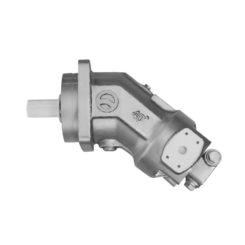
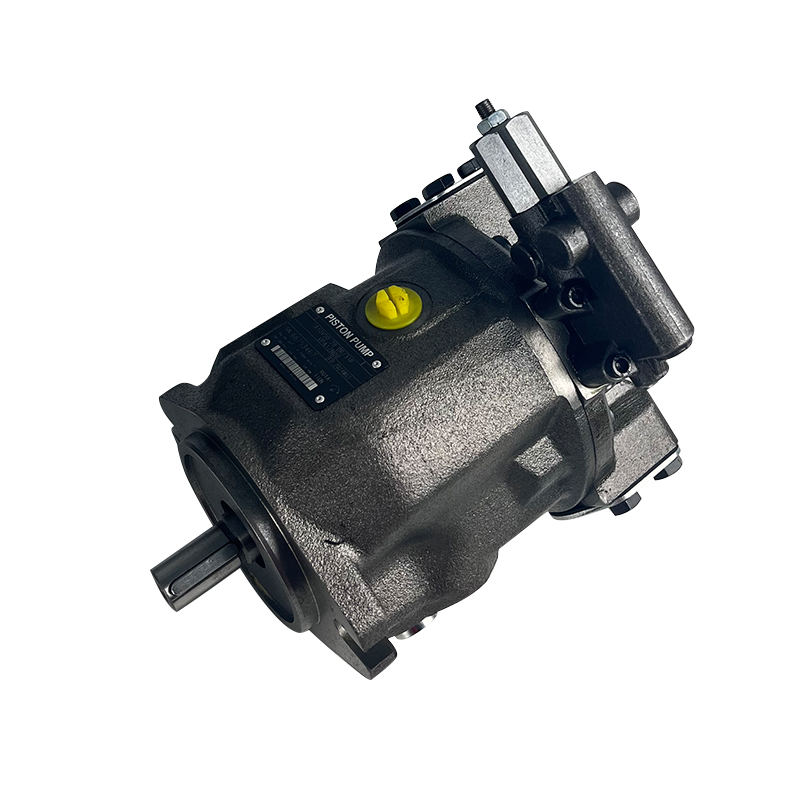
Piston pump troubleshooting: Piston pumps are high-performance units that demand clean fluid and careful attention to case drain pressure. Excessive case drain pressure — caused by a blocked or undersized case drain line — forces fluid past the shaft seal and causes seal failure. Always verify that the case drain line returns to the reservoir above the fluid level and is not creating back pressure. Piston pump noise that increases with pressure indicates worn slipper pads on the pistons, which lose their hydrodynamic film at high pressure. Milky or cloudy fluid in a piston pump case drain sample indicates water contamination, which dramatically accelerates bearing and piston bore wear and requires immediate fluid replacement and system investigation to find the water ingress point.
For both pump types, the single most effective diagnostic action before disassembly is a case drain flow measurement. Normal case drain flow is typically 1 to 5% of rated pump displacement. Case drain flow exceeding 10% of rated output is a reliable indicator that the pump has worn beyond its serviceable range, regardless of whether the external symptoms are severe.
Diagnostic Tools Every Technician Should Use
Effective hydraulic troubleshooting requires more than visual inspection. The following instruments provide the quantitative data needed to distinguish between components that are marginally degraded and those that have genuinely failed.
A calibrated hydraulic pressure gauge with an appropriate range (typically 0–400 bar for industrial systems) and a snubber fitting to protect the gauge from pressure spikes is the most fundamental diagnostic instrument. Pressure readings at defined test points, compared against system specifications, isolate faults to specific circuit sections in minutes. Every hydraulic system should have test point fittings installed at the pump outlet, upstream and downstream of each major valve block, and at each actuator port.
A portable hydraulic flow meter — installed inline using quick-connect test fittings — provides flow measurement that pressure gauges alone cannot give. Flow data confirms pump output, identifies internal leakage across valves and actuators, and verifies that flow control settings match the system specification. Turbine-type inline meters are accurate, compact, and suitable for most industrial troubleshooting tasks.
An infrared thermometer or thermal imaging camera is invaluable for locating heat sources without physical contact. Scanning component surfaces while the system is running reveals which valve is dumping heat to tank (indicating continuous bypassing), which section of piping is running hot (indicating a flow restriction), and whether the cooler is functioning symmetrically. An accumulator can be checked for pre-charge integrity by scanning the shell during cycling — a properly charged accumulator will show a clear temperature boundary between the gas section and the oil section.
A portable particle counter or contamination test kit provides a quantitative cleanliness level reading in ISO 4406 format. This reading tells you definitively whether the fluid cleanliness is within the specification required by the most sensitive component in the system. Many hydraulic problems attributed to component failure are actually contamination-induced wear that will recur if the fluid is not brought within specification before new parts are installed.
Preventive Maintenance to Avoid Repeat Failures
The most effective hydraulic troubleshooting is the kind that prevents failures from occurring in the first place. A structured preventive maintenance program reduces unplanned downtime, extends component service life, and provides the baseline data that makes future troubleshooting faster and more accurate.
Fluid analysis is the cornerstone of hydraulic preventive maintenance. Sending a fluid sample for laboratory analysis every 500 to 1,000 operating hours provides data on viscosity drift, oxidation products, water content, and wear metal concentrations. Rising iron or copper concentrations in the fluid signal that a specific component is wearing internally — often weeks or months before the wear produces a detectable performance symptom. Acting on wear metal data allows planned component replacement during scheduled downtime rather than emergency repair during production.
Filter service intervals should be based on differential pressure indicators rather than fixed calendar intervals. A filter that reaches its bypass indicator pressure after 300 hours in a contaminated environment needs replacement at 300 hours, not at the standard 500-hour interval. Install differential pressure indicators on all suction, pressure, and return filters and inspect them at every daily equipment check. A filter that bypasses allows unfiltered fluid to circulate through the system, accelerating wear in every downstream component simultaneously.
Regular system inspections should include checking fluid level and condition, listening for changes in pump noise, checking all hose and fitting connections for early-stage weeping, verifying relief valve settings have not drifted, and recording pressure and temperature readings for trend comparison. A 15-minute inspection at each scheduled service interval, combined with a written record of findings, transforms hydraulic maintenance from a reactive discipline into a predictive one — and virtually eliminates the surprise failures that cause the most costly production interruptions.