English
 русский
 Español
 عربى
عربى

Content
What Is an External Gear Pump
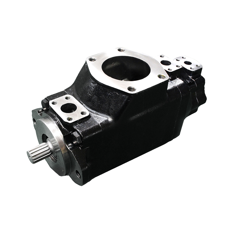
An external gear pump is a type of positive displacement hydraulic pump that moves fluid by trapping it between the teeth of two externally meshing gears and the inner wall of the pump housing. It is one of the oldest and most widely used pump designs in hydraulic engineering, valued for its mechanical simplicity, broad operating range, and reliable performance across demanding industrial environments.
The pump consists of four primary components: a drive gear connected directly to the power source, a driven gear that rotates in the opposite direction through mesh contact, a close-tolerance housing that encloses both gears, and bearing blocks or side plates that seal the gear faces and maintain the precise clearances required for efficient fluid transfer. There are no valves, no variable geometry elements, and no complex internal mechanisms — the geometry of the gear teeth and housing does all the work.
This structural simplicity is one of the external gear pump's defining commercial advantages. With fewer parts than almost any other hydraulic pump type, it is less expensive to manufacture, easier to service in the field, and more tolerant of contaminated or high-viscosity fluids that would damage more delicate pump designs.
How an External Gear Pump Works
The operating principle of an external gear pump follows a continuous three-phase cycle that repeats with every revolution of the drive shaft.
Phase 1 — Intake: As the two gears rotate away from each other on the inlet side of the pump, the unmeshing teeth create an expanding volume between the gear tooth profiles, the housing wall, and the bearing block surfaces. This expanding volume generates a partial vacuum at the inlet port. Atmospheric pressure acting on the fluid in the reservoir pushes fluid into this low-pressure zone, filling the spaces between the gear teeth on both gears.
Phase 2 — Transfer: The fluid trapped in the tooth spaces is carried around the outside of both gears — between the gear teeth and the housing wall — from the inlet side to the outlet side. Critically, the fluid does not pass through the mesh point between the two gears. The close tolerance between the gear tips and the housing bore prevents fluid from leaking back, ensuring that virtually all of the captured volume is transported forward with each revolution.
Phase 3 — Discharge: As the gear teeth begin to mesh together again on the outlet side, they progressively reduce the available volume between them, squeezing the trapped fluid out through the discharge port at high pressure. The meshing action is continuous and smooth, producing a relatively steady flow compared to piston-based displacement pumps.
Because the volume displaced per revolution is fixed by the gear geometry, output flow is directly proportional to rotational speed. Doubling the shaft speed doubles the flow rate. This predictable, linear relationship makes external gear pumps straightforward to specify and control in system design.
Key Performance Characteristics
Understanding the operating envelope of an external gear pump is essential for matching it correctly to a hydraulic system. The following parameters define where external gear pumps perform best — and where their limitations appear.
Pressure range: Standard external gear pumps operate comfortably in the 150 to 250 bar (2,200 to 3,600 psi) range. High-specification industrial designs can reach 300 bar (4,350 psi) in sustained operation. Above these thresholds, internal leakage across the gear-to-housing clearances increases significantly, reducing volumetric efficiency and generating heat. For sustained very-high-pressure duties above 350 bar, piston pumps are generally the more appropriate selection.
Flow rates and displacement: Displacement is determined by gear width, pitch circle diameter, and tooth profile. Commercial units range from below 1 cc/rev for precision metering applications to over 200 cc/rev for high-flow mobile hydraulic systems. Flow rates from a single pump unit typically span 2 to 250 liters per minute at rated speed, with tandem or multiple pump assemblies capable of combining flows from separate sections on a common drive shaft.
Viscosity range: External gear pumps handle a very wide viscosity range — typically 10 to 300 centistokes (cSt) — making them suitable for standard hydraulic oils, gear oils, fuel oils, and various industrial process fluids. Their ability to pump high-viscosity fluids without the risk of cavitation that affects vane pump designs is a significant operational advantage in cold-start conditions or when using thicker fluid grades.
Noise and pulsation: External gear pumps produce more audible noise than vane pumps of equivalent displacement, primarily due to the gear meshing frequency and the discrete pressure pulses generated as each tooth pair engages and disengages. Gear tooth profile optimization, helical gear designs, and acoustic housings can reduce noise levels, but inherent gear mesh noise remains a characteristic of the design that system engineers should account for in noise-sensitive installations.
Self-priming capability: External gear pumps are self-priming and can draw fluid from below the pump centerline, provided the suction line is sized correctly and the fluid viscosity is within range. This characteristic simplifies reservoir placement and reduces installation constraints in mobile equipment where tank positioning is often dictated by vehicle geometry.
Common Applications
The combination of simplicity, cost-effectiveness, and reliable positive displacement output has made external gear pumps the default choice across a broad range of industrial and mobile hydraulic applications.
Mobile hydraulics and construction equipment: Excavators, wheel loaders, telehandlers, and agricultural tractors rely on external gear pumps to power steering circuits, implement hydraulics, and auxiliary functions. Their robustness in environments with vibration, contaminated fluid, and wide temperature swings makes them a natural fit for equipment operating far from maintenance facilities.
Lubrication systems: Machine tools, gearboxes, compressors, and engines use external gear pumps as lubrication oil pumps. The continuous, pulse-free delivery at lower pressures required for lubrication circuits aligns precisely with the pump's output characteristics, and the positive displacement nature guarantees oil delivery even at low speeds during start-up — the critical period when bearing protection is most important.
Hydraulic power units (HPUs): In stationary industrial power units, external gear pumps provide the primary flow source for clamping, forming, and actuation systems in press machinery, injection molding equipment, and material handling systems. Their compact size relative to their output and straightforward maintenance profile reduces the total cost of ownership over extended service life.
Metering and fluid transfer: Because output flow is directly proportional to speed and highly repeatable, external gear pumps are widely used in chemical dosing systems, paint and coating applicators, and food-grade fluid transfer systems where accurate, continuous delivery of a measured volume per unit time is required.
Agricultural machinery: Tractors depend on engine-driven external gear pumps to supply flow to rear linkage hydraulics, remote cylinder circuits, and power steering. The pump's ability to self-prime and operate across a wide speed range — from low idle to full engine speed — suits the variable operating conditions inherent in agricultural work cycles.
External Gear Pump vs Other Hydraulic Pump Types
Selecting the right pump type for a hydraulic system requires understanding how external gear pumps compare to the alternatives across the key performance dimensions of pressure, efficiency, noise, and cost.
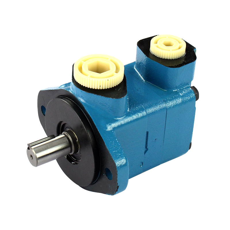
External gear pump vs vane pump: Vane pumps operate on a different displacement principle — spring-loaded or pressure-loaded vanes slide in and out of slots in a rotor, creating variable chambers between the rotor, vanes, and cam ring. Vane pumps generally produce lower noise levels than external gear pumps of similar displacement, making them preferred in noise-sensitive machine tool and industrial press applications. However, vane pumps are more sensitive to fluid contamination and require a minimum inlet viscosity to maintain adequate vane lubrication. External gear pumps tolerate a wider viscosity range and are less sensitive to fluid cleanliness, giving them an advantage in mobile equipment and applications where fluid condition is harder to control. For low-to-medium pressure duties where noise is a priority, vane pumps are often the better choice; where robustness and viscosity flexibility matter more, external gear pumps hold the advantage.
External gear pump vs piston pump: Piston pumps are the high-performance alternative for applications demanding continuous operation at pressures above 250 bar, high volumetric efficiency over a wide speed range, or variable displacement to match system demand. They achieve efficiencies of 90 to 95% in optimal conditions, compared to 80 to 90% for external gear pumps, and can sustain operation at 350 to 450 bar for demanding industrial cycles. The tradeoff is significantly higher unit cost, greater sensitivity to fluid cleanliness, and more complex maintenance requirements. External gear pumps remain the economically rational choice for fixed-displacement applications at moderate pressures where the higher acquisition and maintenance cost of a piston pump is not justified by performance requirements.
| Parameter | External Gear Pump | Vane Pump | Piston Pump |
|---|---|---|---|
| Max. operating pressure | Up to 300 bar | Up to 250 bar | Up to 450 bar |
| Volumetric efficiency | 80–90% | 85–92% | 90–95% |
| Noise level | Medium–High | Low–Medium | Medium |
| Viscosity tolerance | Wide (10–300 cSt) | Moderate (16–160 cSt) | Narrow (10–100 cSt) |
| Contamination sensitivity | Low | Medium | High |
| Relative unit cost | Low | Medium | High |
| Variable displacement | No | Some models | Yes |
How to Select the Right External Gear Pump
Specifying an external gear pump correctly requires working through several interdependent parameters in sequence. Starting with an undersized or oversized pump creates efficiency and reliability problems that are difficult to correct without replacing the unit.
Step 1 — Define required flow rate. Calculate the total flow demand of all actuators in the system, accounting for simultaneous operation where applicable. Express this as liters per minute (L/min) at the intended operating speed. Since flow is proportional to speed and displacement, select a displacement (cc/rev) that delivers the required flow at the design shaft speed with a 10 to 15% margin to allow for volumetric losses.
Step 2 — Confirm system pressure requirements. Identify the maximum working pressure the pump must sustain, including transient pressure spikes from load impacts or valve switching. Ensure the selected pump's rated continuous pressure exceeds the system maximum working pressure, and that its peak pressure rating accommodates expected spikes. Operating consistently near the pump's maximum rated pressure accelerates gear and bearing wear.
Step 3 — Verify fluid viscosity compatibility. Check the operating viscosity of the hydraulic fluid at both minimum (hot, low-load) and maximum (cold start) operating temperatures. The fluid viscosity must remain within the pump's specified range throughout the operating cycle. If cold-start viscosity is expected to exceed 300 cSt, a pre-heating strategy or a pump designed for higher inlet viscosity should be considered.
Step 4 — Check shaft speed and drive configuration. External gear pumps have both minimum and maximum speed ratings. Operating below minimum speed risks inadequate self-priming and poor internal lubrication. Operating above maximum speed causes cavitation and accelerated bearing wear. Confirm that the drive speed — whether from an electric motor, engine PTO, or gearbox output — falls within the pump's rated speed range across all operating conditions.
Step 5 — Consider mounting and port configuration. Gear pumps are available in SAE, ISO, and manufacturer-specific flange patterns, and with various shaft configurations (keyed, splined, or tapered). Confirm that the selected pump's mounting interface is compatible with the available drive configuration and that the port sizes match the system's line sizing to avoid excessive inlet restriction.
Maintenance and Common Failure Modes
External gear pumps are among the most reliable components in a hydraulic system, but they are not maintenance-free. Understanding the most common failure mechanisms helps engineers establish appropriate service intervals and identify problems before they become costly.
Adhesive wear on gear faces and housing bore is the most common wear mechanism in external gear pumps operating within their design envelope. Over time, the close-tolerance surfaces between gear tips and housing develop microscopic wear that increases internal clearances, reducing volumetric efficiency. A pump that was delivering 95% efficiency when new may drop to 80% or below after extended service, resulting in higher fluid temperatures and reduced actuator performance. Regular monitoring of system flow output and fluid temperature trends provides early warning of efficiency degradation before the pump fails completely.
Cavitation occurs when the fluid pressure at the pump inlet falls below the vapor pressure of the fluid, causing vapor bubbles to form in the low-pressure zones and then collapse violently as they enter higher-pressure regions. The implosion energy erodes gear tooth surfaces and housing walls, producing a characteristic pitting pattern visible on inspection. Cavitation is typically caused by an undersized or restricted suction line, excessive fluid viscosity at cold start, a clogged suction filter, or operating the pump at speeds above its design rating. Preventing cavitation requires correct suction line sizing, regular filter maintenance, and appropriate cold-start procedures.
Contamination-induced abrasion affects the gear tooth profiles, bearing surfaces, and housing bore when hard particles above the system's filtration threshold enter the pump. Unlike piston pumps, external gear pumps are relatively tolerant of moderate contamination, but sustained operation with heavily contaminated fluid causes accelerated wear across all internal surfaces. Maintaining the hydraulic fluid at ISO cleanliness code 16/14/11 or better extends pump service life significantly and reduces unplanned downtime.
Shaft seal failure is a common maintenance item, particularly on pumps subject to elevated case pressure or thermal cycling. A weeping shaft seal is usually the first sign of seal degradation and should be addressed before the leak progresses to external fluid loss or air ingestion through the damaged seal lip on the return stroke. Shaft seals are low-cost components, and replacing them at the first sign of weeping is far more economical than allowing the problem to develop into bearing damage or housing contamination.
As a general maintenance guideline, inspect suction filters every 500 to 1,000 operating hours, change hydraulic fluid and return-line filters according to the system manufacturer's schedule, and monitor pump outlet pressure and temperature at each scheduled service interval to trend efficiency over time.